WELCOME!
|
Welcome to the project website for BraceFace, our team's quarter-end project for ME 218B at Stanford University!
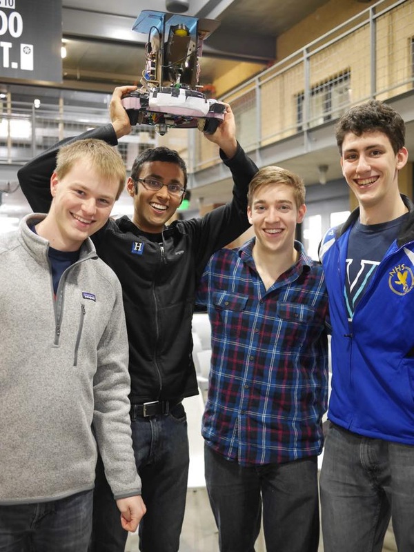
Lovingly called braceface for the sheet metal bumper on the front, our bot was the first to navigate the course during grading - as seen in the video below. See below for the project description and team member information, and see the tabs above for design solutions. Enjoy! The fastest way to get over the finish-line? Fall forward! (yes it counted, no it didn't shave off significant time)
|
|
The Challenge
The goal of the project was to design and build a robot capable of racing around an obstacle course in the fastest amount of time. The race course layout and dimensions can be seen below:
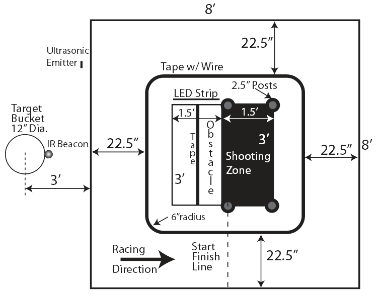
In addition to the components shown above, there was a camera suspended directly above the center of the course capable of tracking and transmitting data to each of the robots through Synchronous Serial Interface (SSI) communication. This camera system was referred to as the DRS, (DrEd Reckoning System). The information relayed by the DRS included position data, (x, y, theta orientation), the status of the race, (start, caution, end), and feedback on whether a shot has been made or the obstacle has been traversed.
The black tape loop contained an embedded wire carrying 100mA modulated by a 20kHz sine wave.
The IR Beacon attached to the target bucket was always on to allow robots to orient to the target.
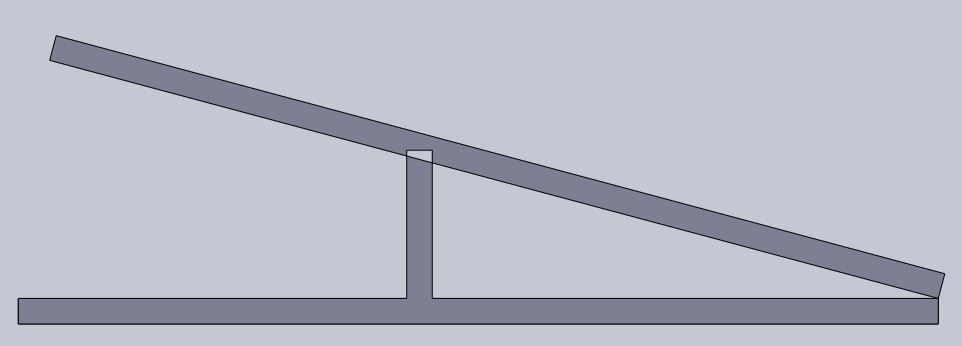
The obstacle was constructed such that it was always "down" at the end nearest the LED strip with an incline of 15 degrees. As a robot moved along the obstacle, it would swing "up" at a 20 degree incline with the edge nearest the start/finish line touching the ground. Once the robot left the edge, the obstacle would swing back to the "down" position. The LED strip and Ultrasonic emitter were set to turn on when the obstacle reached the "up" position. The images below are oriented as if viewing the obstacle from the shooting zone. (15 degree incline on left, 20 degree decline on right)
The black tape loop contained an embedded wire carrying 100mA modulated by a 20kHz sine wave.
The IR Beacon attached to the target bucket was always on to allow robots to orient to the target.
The obstacle was constructed such that it was always "down" at the end nearest the LED strip with an incline of 15 degrees. As a robot moved along the obstacle, it would swing "up" at a 20 degree incline with the edge nearest the start/finish line touching the ground. Once the robot left the edge, the obstacle would swing back to the "down" position. The LED strip and Ultrasonic emitter were set to turn on when the obstacle reached the "up" position. The images below are oriented as if viewing the obstacle from the shooting zone. (15 degree incline on left, 20 degree decline on right)
|

|
The three qualifications for finishing a race were as follows:
1. Complete the specified number of laps around the posts (between 3 and 5 laps)
2. Successfully shoot a ball from the shooting zone into the target bucket
3. Cross the see-saw obstacle
Each of the robots was required to be a stand-alone package, meaning no external power sources or user tethers or commands were allowed. In compliance with this specification, the robots needed "on-board" power and were limited to a maximum of two (2) 7.2V NiCd battery packs available for purchase in the SPDL.
The full project description is provided in the link below.
| me218bprojectdescription.pdf |
The Function
So what’s in Braceface?!
Our robot has multiple components to it. First, we have our TIVA microcontroller which acts as the brain of our robot, telling us what commands to execute and when to excecute them. It does this via a hierarchical state machine. Second, we have an SSI-based query system that communicates with the staff’s DRS (position reckoning system) to provide us with our position and orientation, as well as game data (start the race, stop the race, etc). Third, we have a shooter composed of a flywheel, ball holder, and servo-loading mechanism. This is used to fire our ball towards the target. Fourth, we have multiple sensors on our robot that are used to do everything from detecting the IR beacon marking the target to telling us how fast our wheels our going. The latter function is part of our nested PID control system. Fifth, we have a robust drivetrain that ensures steady and smooth output from the motors. Finally, our robot’s joins all of these parts together with very robust physical structure (as we witnessed from its survival of > 50 faceplants).
Cut the dorkiness, give me the high-level picture!
Our robot is holding position on the start line, waiting for the start signal. Once it receives the signal, we set our motors' speed to a specific RPM and our encoder, sensors, and PID control loop ensure that our motors are capable of matching our desired output. As we approach the first corner of the board, our robot’s position will trigger an event checker that is looking for the turning region. We then enter a ‘turning’ state, doing a wide turn until the desired orientation has been achieved. Once achieved, we transition to the 2nd leg of the course. During our straight legs, we have a control law that ensures we stay close to the middle of the leg and adjusts the speed on our motors to compensate if we deviate too far. As we merrily coast down the 2nd leg, we look for the start of the shooting sequence using an event checker. Once we have crossed a certain y-value, our robot stops and begins to turn towards the shooting zone. Once turned, it drives about halfway into the shooting zone before it stops and rotates towards the target, looking for an IR Signal to align our shooter. Upon acquisition of the IR signal, it starts the flywheel and our servo loads a ball into the firing tube. After a short moment, it executes a full push into the tube. The ball then swishes into the bucket and our robot fades back towards the 2nd leg. Once it reaches the leg, it rotates to align with leg 2 and continues on its way towards leg 3. Once it reaches another specific y-value, again via an event checker, it enters another ‘turning’ state and begins a wide turn until it reaches the orientation of leg 3. It then continues to drive straight until it reaches a certain x-value, via an event checker, that triggers the obstacle sequence. We first slow down on approach to the obstacle so we don’t drive past the center of the obstacle. Once we reach the center of the obstacle path, we rotate until we are oriented parallel to the obstacle path and then begin to drive slowly over the obstacle (to avoid spinning out of control). As we traverse the halfway point of the obstacle, the obstacle will fall down and we slide down very rapidly. Our steel brace, forged in the fires of the PRL, acts to break our fall and give us a smooth slide down. Once we have exited the obstacle, we rotate until we are oriented parallel to the 1st leg of the race and then repeat the process, shooting only if we haven't yet made a shot, until the race is complete.
The Team
Greg Campbell
I am from Newtown, CT and completed my undergraduate studies at Villanova University, which is right outside Philadelphia. I am interested in mechatronics, controls, and robotics within Mechanical Engineering. In my free time I enjoy playing team sports, particularly soccer and basketball. |

Quinton Ford
I received my undergraduate degree in mechanical engineering from the University of Illinois at Urbana-Champaign in May 2014. My hometown is Downers Grove, IL which is located a few miles outside Chicago and is where I have lived my entire life. The past three summers I have worked in the Loop for ESD, a global consulting-engineering firm specializing in mechanical, electrical, and plumbing building systems engineering. I am a huge baseball and college basketball fan, with my favorite teams being the St. Louis Cardinals and the Illinois Fighting Illini. |

Samir Patel
Hi all! My name is Samir Patel and I am a first year MSME student. I hail from Tampa, Florida (go Rays/Bucs/Lightning!) and obtained my Bachelor's degree in Engineering Sciences from Harvard College. While not engineering away, I absolutely love to follow/play/watch/liveandbreathe soccer. I also happen to be a huge foodie---I make a mean hummus and guacamole! |

Joshua Siegel
I'm originally from Cedar Rapids, Iowa, did undergrad here in Biomechanical Engineering and Slavic Literature, now doing masters in ME. Aside from academics I enjoy being a part of Stanford Jump Rope. |
